Zramo 104 Experiments

Zramo 104 Fifine Experimental Mods
Tuesday, May 31, 2022
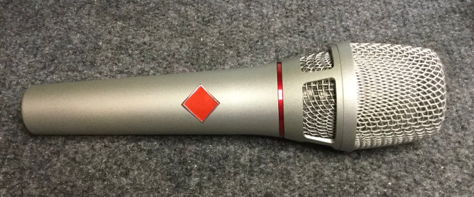
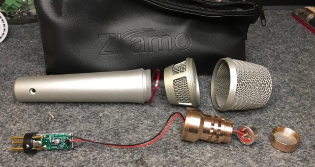
Today we get back to the second Zramo mic from Amazon, the “104 Fifine” model which sells for just under $10. It comes in a vinyl pouch in a cardboard box. No cable, no shock mount, no wind screen.
The first item to try is replacing the capsule with one of the 34mm “brass” electrets from AliExpress. This required cutting the capsule holder off of the inner brass structure.
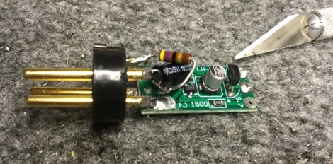
Cut Here

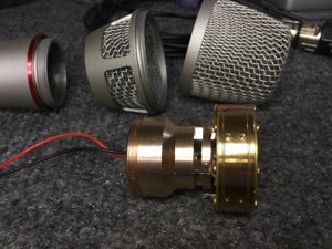
The 34mm capsule was attached with glue and set aside to cure for a day. The long wires were unsoldered from the circuit board and soldered to the new capsule first.
That brings us to the electronics. The original circuit is very simple, a K596 JFET, a 2N5401 PNP transistor, 2 resistors, and one capacitor.
It looks a little like a very stripped down Schoctava, but there are important differences. Most obvious, there is nothing connected to pin 3 of the XLR connector. For noise pickup in the mic cable to cancel, pins 2 & 3 need to have roughly the same source impedance. Second problem is that in the Schoctava, the JFET is hooked up as a source follower, which does not invert the signal. Here, the JFET is hooked up as a common source amplifier, which does invert the signal. That makes the signal at the output on pin 2 out of phase with standard studio mics. Third possible problem is gain. The FET will amplify the signal by 12 to 20dB, and may distort on loud sounds.
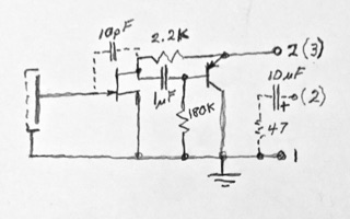
So here are the fixes I tried. Fixing the phase meant swapping the output from pin 2 to pin 3 of the XLR. Not easy, but it can be done by unsoldering the circuit board from the connector and rotating it 90° so the output is at pin 3.
Pin 2 then has a 10uF capacitor and 47Ω resistor added to ground for an impedance balance with pin 3. (Drawn in dashed lines in the schematic above.)
Now we’re getting somewhere.
Time to try it out. It sounds OK on the workbench, so let’s go to the computer and the M4 interface. Not bad, actually. It’s pretty loud. Screaming into the mic like a punk rocker is probably gonna clip like crazy. So let’s try the trick we used on the TL/C mics, and add a feedback cap from drain to gate of the FET. A 10pF NP0 ceramic between the pad marked 9.7 and the + input should do nicely. (Drawn in dashed lines on the schematic.)
Yep, that cut the sensitivity by about 15 dB. But now, there is clicking and buzzing noise from the computer’s WiFi and my cell phone, because the preamp gain had to be turned up, and noise picked up on the mic cable is getting fed into and amplified by the FET as well. OOPS!
OK, let’s add .001 uF RF bypass caps from pin 1 to pin 3 and pin 1 to pin 2 of the XLR. Hmmm... That made the interference even worse! OK, check for paint on the mic body preventing some parts from connecting to ground. Nope, that’s not the problem. So remove the RF bypass caps. Better, but still noisy. Remove the 10pF NFB cap. Better again, but the mic is very sensitive, and now that I listen for it, there is RF noise faintly in the background.
Hmmm... The mic in this state is usable for voiceover work, but the capsule is very sensitive to plosives and sibilants. Adding a couple of layers of cloth from a sock helped with wind noise, P’s, and S’es. So the capsule is usable in a vocal mic, but sensitivity is still higher than I’d like.
Gain could be reduced by adding source degeneration to the FET, or capacitive loading of the capsule, but we’d again face S/N issues. So the 2-transistor Chinese circuit falls short of real pro studio performance. Ultimately, these “104” clone bodies wound up with Schoeps-sh circuits, JFET follower + PNP splitter and outputs using some other small Chinese circuit boards. (See here.) Much more complex, but balanced output, with good RF filtering, and very low distortion.
Anyway, here’s what the mic sounded like with the modded OEM 2-transistor circuit:

