A Few More China Mic PCBs Measured

More China Mics
Sunday, October 16, 2022
This is a note about some of the Chinese Mic printed circuit boards sold on the bay, Amazon, and AliEx.
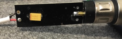
There are some small, slim PCBs for use in pencil style mics. Some are black, some are red, or green. I bought a few black ones from different vendors, different board layouts and parts on each. They vary in frequency response and distortion considerably, though all are based on the BM800 circuit. Some have the wrong value resistors and or capacitors on the board. Most work after a fashion, but may be severely lacking in bass, and distortion can be very high.
Here are examples:
BM700 Stock
Modded “ZRAMO”
Schoeps
Black pencil “XJM0013A”
Black pencil “DA JIA DIAN ZI”
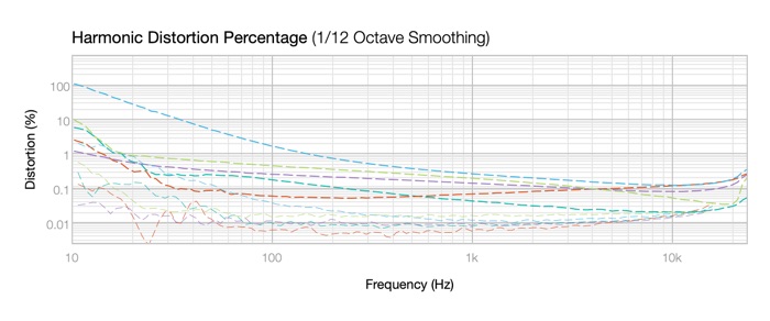
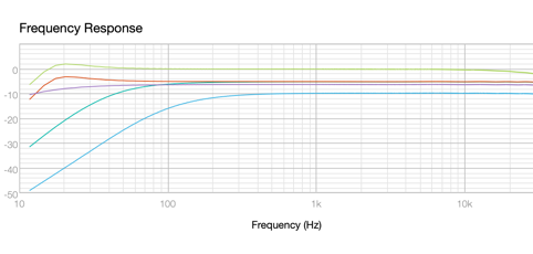
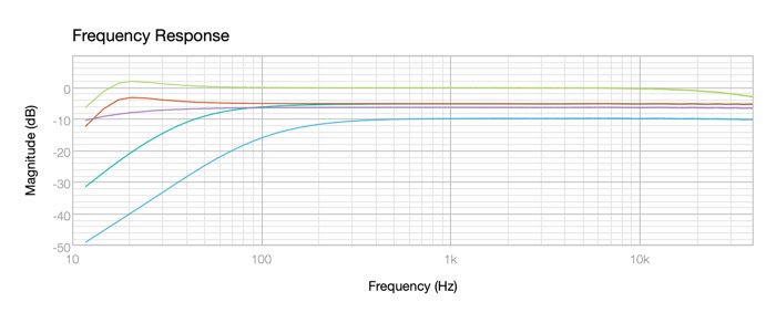
The graphs show the narrow “pencil” mic boards have strongly rolled off bass response. (For close talking?) The Universal China Mic circuit has a Sallen-Key high pass filter designed in, and some mics have it set as high as 200Hz. These will not sound good on many instruments. Remember, middle C is 261Hz.
Distortion ranges from a fraction of a percent for the Schoeps and modded PCB to 30% at 20Hz and 100% at 10Hz. Yikes!
The modded ZRAMO is a BM800 style PCB with added power filtering and the JFET reconfigured as a source follower. The Schoeps uses a conventional JFET input / phase splitter and PNP follower outputs. The black pencil style PCBs have the UCM circuit with various changed component values. They are identified by the label on the bag they came in or printed on the board itself.
UPDATE:
Finally found the problem with the pencil mic boards bass response. As suspected it’s so big and obvious nobody noticed.
The PNP phase splitter acts as if its input impedance is about 1K, where it’s clearly a 120K and 82K resistor in parallel, call it 50K or so. Pulled resistors off a board and measured ‘em. They’re OK. The emitter load is 2.2K to ground, and the collector load is 2.2K to the 9V supply. I was measuring the resistors for the umpteenth time trying to figure out why the transistor was barely conducting, when it came to me. Wait - this is a PNP transistor. Emitter positive, collector negative. The board is laid out with emitter and collector swapped. Double check. Yep! that’s it. Shit. Three PCB layouts from three different companies with the same goof. SMT too, so not easy to swap pins.
China really is monkey see, monkey do.
Early transistors where emitter and collector were spots of dopant on the base slab were like some JFETs, symmetrical. Didn’t matter which was which. Modern transistors have very specific emitter and collector structures. But they still transist if swapped. Sort of.
Fixes: a couple of possibilities; tack a PNP with bent leads to the teeny little pads, or put in an NPN SMT transistor. I don’t have SMT transistors on hand. Wonder if Amazon has a SMT transistor kit with 2-day delivery?
A bit of hackery later:
An NPN transistor works, but bias is wrong, and changing 2 resistors plus the transistor is more work than changing just the transistor.
So here’s MY recipe for using these pencil style mic boards from China.
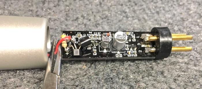
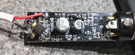
Here’s a different board with 4.7K, K596 FET, and BC557B PNP transistors tacked to it. The XLR connector also had to be moved so pins are on the component side of the board to make it fit. There is a 47uF cap on the back side of the printed circuit. Is it really worth the hassle?
In my case, it was a challenge. A puzzle to be solved. Can this POS be made to work?
So be aware that just because a board appears to have a familiar circuit layout, you need to check how it performs. Some are easily modded for acceptable performance. Some aren’t, unless you are proficient at surface mount rework. Fixing these with a fine tip soldering iron is a royal PITA.
I can’t recommend these to the average DIY hobbyist. They kinda sorta work, but not very well, and they’re hard to make work right.
Boards came in the mail today from a different supplier, and they have the same problem. I dug some green boards from 10 years ago out of the closet, and they are wrong. A friend sent photos of the red PCBs, and it looks like they’re wrong too. I wonder if anyone who makes these boards has ever tested one? I wonder if he would know whether it worked properly? Unfortunately such problems are common. Buyer be aware.
After repair distortion is low, and bass response extends to 40 or 20 Hz depending on the capacitors in the high pass filter. With typical 16mm cardioid electret capsules, a foam ball or screen style pop filter is mandatory for vocals. P’s and T’s will be LOUD. But small electrets aren’t replacements for a dynamic vocal mic. They work on instruments, as overheads, and as room mics like you would use any other small condenser.
First, add a 47uF / 16V solid tantalum capacitor between ground and the 9V supply to filter noise from the regulator transistor.
Make a solder point to 9V supply.
Remove R1 (2.2K)
Add a 3.3K or 4.7K resistor between + and - input pads.
Remove Q1 and replace with a PNP (2N5401 or BC557B for instance) with leads bent as shown.
C B E


The board is suitable for use with capsules with 3 terminals and internal FETs by connecting the drain to the 9V supply (red wire in photo), source to the + pad (black wire) and ground to the - pad (shield wire). For capsules without built-in FETs, I use either a 2SK596B FET mounted at the capsule, or a J305 and 1G ohm resistor at the capsule. Connect them same as the built-in FET.
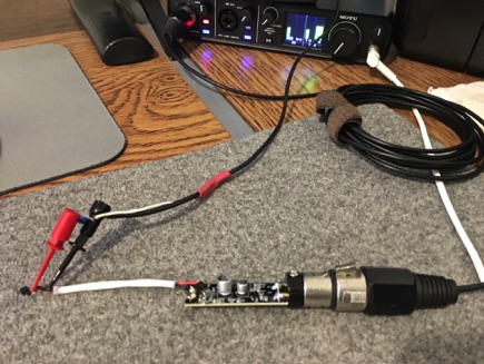
Board and K596 FET being tested with 40dB attenuator cable and computer interface.