Mic Circuits From Simple to Professional

Circuits - Simple to Professional
Friday, February 5, 2021

There are lots of condenser microphone circuits around suitable for DIY and hobbyist construction. Just for fun, let’s run through a few, starting with the simplest and work up to the classic Schoeps. All of these are meant to plug into a standard XLR mic input and operate on 48V phantom power.
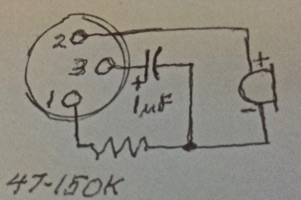
The simplest condenser mic circuit is a single JFET, one of the ones made for electret mics with an internal diode to provide the gate reference, one resistor, and one capacitor. It’s covered here and here. It works well with electret capsules with internal FETs as well as electrets using an external FET. Not so hot, however for an externally polarized capsule because the bias voltage for the capsule is not filtered, and any noise on the 48V phantom power supply goes straight out with the audio signal.
The drawing above shows an electret mic where the FET is built into the capsule.
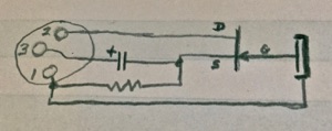
A version with external FET and an externally polarized so called “true condenser” capsule.
The next step in complexity is found in cheap Asian electret mics. The FET may be part of the capsule or mounted on the PCB, which is typically soldered directly to the XLR plug as shown in the photo at the top of the page. Notice that pin 3 of the XLR is not connected to anything, so noise pickup is likely, and the cable impedance is unbalanced. So how can this work? The FET can’t stand more than about 20V. The PNP is turned on hard enough to pull pin 2 down to around 10V. The 2K2 drain load resistor for the FET is “bootstrapped” that is, both ends go
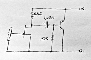
up and down together because the PNP output transistor is an emitter follower with no voltage gain. In theory that should reduce distortion, but as it turns out, there’s enough distortion elsewhere to cover up any benefit.
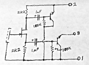
The next improvement would be to double up and make the circuit balanced, so some of the distortion cancels, the impedances on pins 2 & 3 are the same, and both pins carry signal. This still only works with electret capsules and the special FETs with diodes on the gate.
Next in complications, power the FET from the collector current of the output stage as in:
https://www.directap.com/Microphones
At the bottom of the page. Draws less power from 48V, and adds filtering to FET power supply at the expense of 1 more resistor and 2 capacitors.
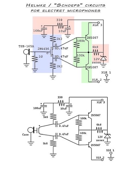
Add a zener diode and another RC filter to the FET power supply, and we have the “Alice” circuit.
It’s covered in depth here, so I won’t go over it again.
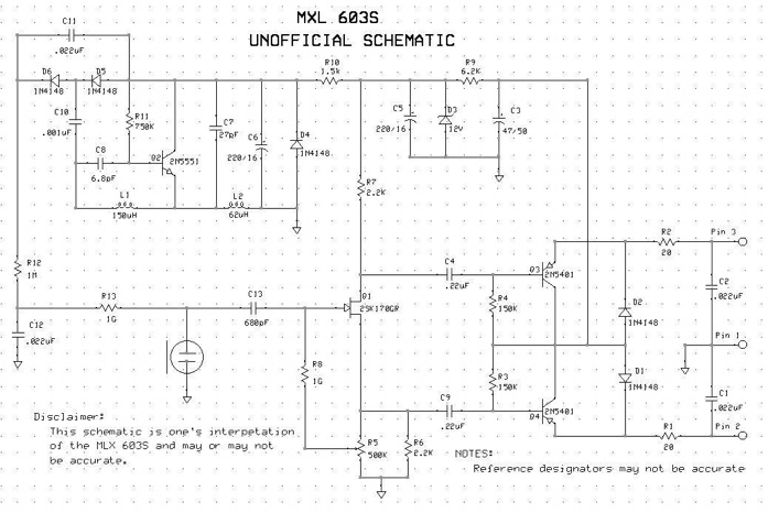
Add a 2N5551 oscillator and voltage doubler to provide 60V or so for polarizing a regular condenser capsule, and we have the classic Schoeps circuit in most of its glory. Admittedly, an MXL 603S is possibly less glorious than an original Schoeps CMC-5, but all the important circuit elements are present.

Capsule without built-in FET
Capsule with built-in FET

