Basic FET Circuits for Mics

Basic FET Microphone Circuits
Thursday, April 23, 2015
For some folks who are new to electronic circuits as applied to capacitor microphones, a quick rundown of some common implementations might be useful. Let’s start with Scott Helmke’s “Alice” mic circuit since it’s about as simple as you can get for a “studio” grade mic.
A brief rundown of some circuits for solid state microphones.
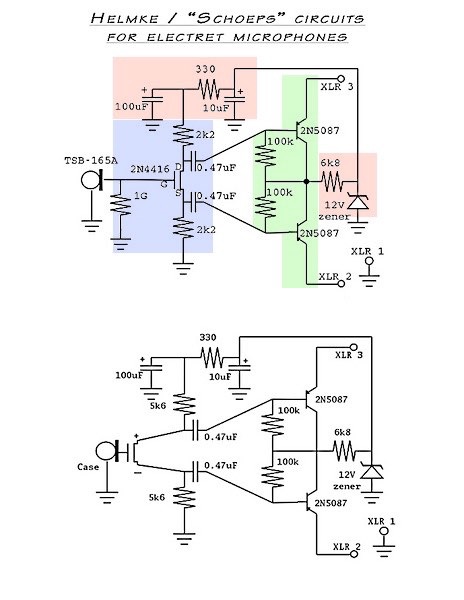
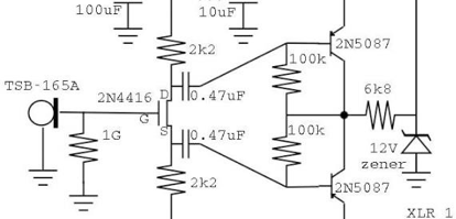
There are three sections, the input stage shaded blue, the output stage shaded green, and the power supply shaded red.
The upper drawing is for an electret capsule without an internal FET. The input stage’s job is to take the extremely small charge variation from the capsule and convert it to a voltage. The capsule is essentially a variable capacitor driven by sound. An electret has a built-in source of charge, usually a thin film of plastic on the backplate with a baked-in charge. When sound moves the diaphragm, the capacitance changes, and this causes electrons to move onto or off of the backplate in order to maintain a constant voltage across
the capacitor, since maintaining voltage is what capacitors do. That small current needs to be boosted many times before it can drive a cable and mic preamp. An FET does the initial current amplification. FETs are basically voltage controlled resistors. The voltage at the gate controls the resistance between source and drain. A very large resistor biases the gate to ground potential. Since this resistor contributes noise, there is a trick here. Notice that the capsule is in parallel with this resistor. Think what a capacitor does. It tries to keep the voltage between its terminals constant. In audio work, that means signals pass thru a cap but DC doesn’t. Here we have a gate resistor which because it’s above absolute zero has a small white noise current due to thermal electron motion. The capsule is connected across the gate resistor, so it will resist the noise voltage, try to hold voltage steady. It’s an RC filter. The capacitor (capsule) is tiny, but if we make the resistor very very large, say a gigohm, the corner frequency is pushed below the audio band, down around 1Hz. In essence, the capsule conducts the resistor noise straight to ground.
The next thing to notice about the input stage is there are identical load resistors on the FET’s source and drain. This creates two outputs from the first stage. The source follows the voltage at the gate almost exactly, since a rising voltage at the gate causes an increase in current from source to drain, which causes the voltage across the source resistor to rise until it cancels out the increase at the gate. Since the same current flows through source and drain, the same voltage drop occurs across the drain resistor, driving its voltage down from the power supply. Thus the drain has a signal the same amplitude but opposite polarity. The net effect is the FET provides a voltage gain of two. Two outputs each of which is equal to the input voltage, but of opposite phase, and at a much lower impedance, roughly the same as the load resistors. The pair of 0.47uF capacitors couple the signals to the output stage.
The output stage looks a bit weird, but that’s because only half of it is in the microphone. The rest of it is inside the mixer or mic preamp. The circuit is a PNP emitter follower which like the source follower has no voltage gain, but has considerable current gain. Because of the 100% local negative feedback, distortion and output impedance is very low. The emitter load resistors are the 6.8K resistors inside your 48V phantom power supply, normally part of your mic preamp. The 100K resistors furnish bias current to the PNPs.
The power supply section supplies about 10-12V for the FET. The 6K8 resistor sets the operating current in the output stage, the zener diode regulates the FET’s supply voltage, and the capacitors and 330 ohm resistor filter noise from the zener and output stage out of the supply.
The lower drawing is for a mic capsule which has an internal FET like many inexpensive electrets.
Now let’s look at another FET microphone circuit.
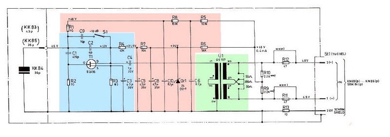
Here we have the original phantom powered mic, the Neumann KM84. This mic has an externally polarized capsule instead of an electret, so there is a path via R9, R10, R5, R8, and R1 for 48V to charge the capsule backplate. T1 is an FET as before. Look at the circuit from the FET’s power source at C5 to ground and trace current flow. T1 is acting like a variable resistor changed by audio. This causes a varying current to flow thru T1, R3 and R4. Now look at R3. It’s paralleled (bypassed is the common term) by C3. C3 is big enough to absorb the current fluctuations at audio frequencies, so it holds the voltage at the source constant. As far as audio goes, the source is grounded. Not so for DC, of course. So R2 and R3 are for DC bias purposes, but are configured so they aren’t in the audio path.
Now let’s gat back to R4 and the FET and the audio current flowing thru them. As T1’s gate voltage rises, resistance from source to drain decreases, the current thru R4 increases, and the voltage at the drain drops. The opposite occurs as gate voltage drops. So we have a signal at the drain opposite in polarity to the input at the gate. For the moment, we’ll ignore C2. C4 is large enough to hold the voltage across itself constant at audio frequencies, so the signal passes on to the transformer primary, and thence out into the world.
Now let’s consider the gain structure. T1, the FET, is configured as a common source voltage amplifier with negative AC feedback from drain to gate. The feedback voltage divider is the capacitors C2 and the capsule, 4pF and 36pF respectively. This is called a charge amplifier. Simplifying the math a bit, the feedback is 4/36, giving a voltage gain of close to 9. The FET output is fed to an 8:1 transformer, which brings the voltage down to 1/8th, steps current up by 8X, and the impedance down by 64X. So the net effect is similar to the Alice mic, no overall voltage gain, but a huge reduction in impedance from roughly a billion ohms at the capsule to about 200 ohms at the XLR connector.
The gain can be reduced roughly 10dB by switching a 15pF cap in parallel with C2.
These sections can be combined in different ways, for instance a charge amplifier driving a phase splitter and PNP output pair, or an FET driving an emitter follower which drives a lower ratio transformer. Look up the MXL 2001 circuit for example. A 2:1 transformer is easier and less expensive to make than a high quality 8:1 tranny.
If you look at the circuit of the karaoke electret mics, its first stage is similar to the KM84 without feedback, giving voltage gain (and a bit of second harmonic distortion) coupled to a PNP phase splitter and a “Schoeps” type PNP output stage.
I hope this explanation is useful. I was surprised when I started analyzing microphones to find the electronics don’t usually provide voltage amplification. It’s all current gain, bringing the impedance down. Occasionally a mic has built-in electronic equalization, most often to tame a capsule resonance at the high end, or to roll off the bottom end of a velocity mic.

