Modding a BM-800 Mic

Modding a BM-800 Mic
Sunday, December 20, 2015
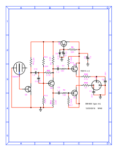
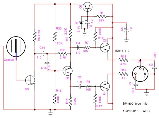
There are several low-cost “Karaoke” electret mics which go by names like BM-700, BM-800, K-5000, E-1000 and so on. All seem to share the same general circuit and even the same printed circuit board. We traced the circuit in one a while ago, and it looks something like this:
A while back we took a look at inexpensive “Karaoke” mics from China. Here we try some mods to get better performance.
Testing revealed that performance wasn’t too bad except for a lot of noise which turned out to come from the voltage regulator. Adding an R-C filter between the regulator transistor Q6 and the input stages helped a lot. That might be all you’d need to do if you’re upgrading to a better electret capsule like a Primo, a JLI TSB2555B, or a Mic-Parts RK-99. See this and following articles.
But what if you’re upgrading to a capsule which requires a polarizing voltage? For those you need to build a little DC-DC step-up converter to supply 50 to 70 volts. It can be built on a bit of perforated pc board and attached to the other side of the chassis rails from the amplifier.
Now our circuit looks something like this:
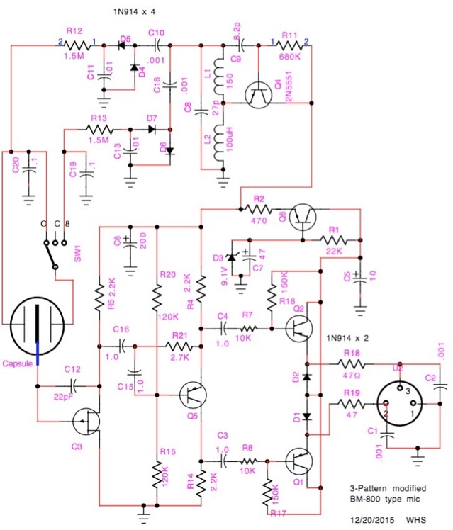
Let’s look at the changes. First, the added R and C noise filter, R2 470Ω and C6 something over 100uF. If it is my mic, I’d replace C5 with something bigger, maybe 100uF / 50V as well.
Then we have a new large diameter capsule with dual diaphragms, capable of cardioid, omnidirectional, and figure-8 pickup. To supply bias voltage for it, there is Hartley oscillator Q4 followed by a pair of voltage doublers making about +65 and -65 volts. A three-position on-off-on switch selects the pattern. The front diaphragm is charged to +65V, and the rear is charged to +65 for omni, disconnected for cardioid, or charged to -65V for fig-8.
The large capsule is more sensitive than the small one which shipped in the mic, and it will overload the input FET unless measures are taken. The K596 FET which is usually used in these mics has diodes protecting the gate, and they will begin to conduct at high signal levels. So C12 is added, converting the circuit to a “charge amplifier”. C12 feeds back a charge opposing that coming from the capsule, and keeps the FET gate at ground potential. Therefore the input becomes a virtual ground and signal is transferred as current instead of voltage as in a “normal” Schoeps input. C12 can range from about 5 to 50 pF, smaller cap giving more gain & sensitivity and less max SPL capability. If your mic overloads too soon, use a larger cap.
Another possibility is to remove Q3 and all parts ahead of Q5. Replace Q5 with a suitable FET with 1 gigohm gate resistor, and lo, you have a more or less standard Schoeps mic circuit.
So how do they stack up? I made one Schoeps with a J305 FET, one with the K596 in a charge amp config, and a charge amp with J305 and 1G gate resistor. Test results:
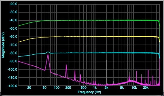
Schoeps (J305 FET) response at 10mV, 1mV, and 100uV input (green yellow blue)
Residual noise (magenta).
Harmonic distortion (grey) at 100mV input
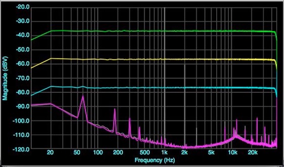
Charge amp (K596 FET) response at 10mV, 1mV, and 100uV input (green yellow blue)
Residual noise (magenta).
Harmonic distortion (grey) at 100mV input
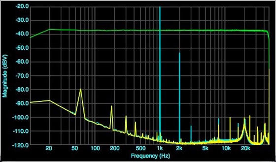
Charge amp (J305 FET) response at 10mV green
Residual noise (Yellow)
Harmonic distortion (blue) at 100mV input
Summary of results: J305 Schoeps is lowest distortion, unity gain impedance converter. The K596 charge amp has about 0.6% second harmonic, almost no 3rd harmonic, and about 3dB gain. A bit warmer or toobish in character. The J305 is unhappy in the C amp circuit, it needs a different biasing setup. Biased properly in a C amp, its distortion will probably lie somewhere between the other two.
The K596 charge amp is pretty easy to implement except for dealing with SMT circuitry. Only 3 or 4 parts to add / change on the printed circuit itself, and building the DC-DC converter if using an externally biased capsule. It makes a capable mic circuit, not quite as quiet and refined as the best out there, but a world better than stock.

