M-AUDIO AUDIO BUDDY

AUDIO BUDDY MIC PRE
Saturday, May 22, 2021
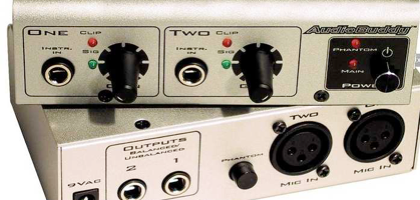
Among my handy gadgets is an Audio Buddy mic preamp. Useful for checking out mics, amplifying a signal via the instrument inputs, feeding the MacBook’s line inputs, etc. While cleaning some old Shure ribbon mics, I plugged them into the A.B. to check that they are still working. They sounded fine, which is a surprise since the listed mic input impedance is 1K ohms. That’s low for the Shures, which prefer something like 2.5K ohms. That set me wondering just what’s inside the box in detail. I had already opened it up and installed a mini stereo headphone jack for convenience when using it for signal tracing and patching into the laptop.
So here’s the lowdown on my Audio Buddy. Note that yours may be different, I probably made a mistake or two, your mileage may vary, and this was done by a trained engineer in a closed laboratory. You mess with yours at your own risk. OK?
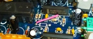
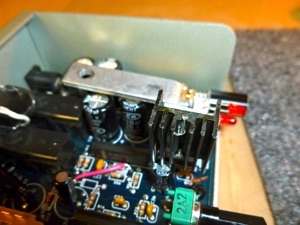
The Audio Buddy from M-Audio is a favorite cheap and cheerful mic preamp and direct box. Its performance is good for the very low price, but there are known issues. I took mine apart to see what’s inside.
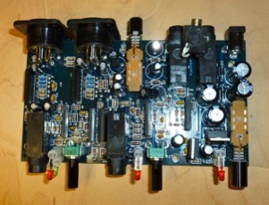
MIDIMan, which became M-Audio, which became part of Avid, designed this gadget using readily available cheap parts, and the designer stuck to the same part values wherever he could. For example, nearly all electrolytic caps are 10 MF / 50 V, and except for the mic pre stages, all circuitry is done with NJM4560L op-amps.
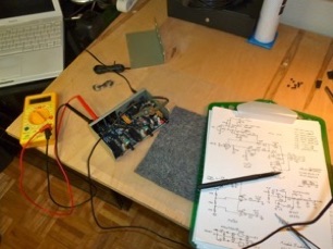
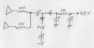
So to get down to the nitty-gritty, here’s a schematic scrawled while poking around with a VOM.
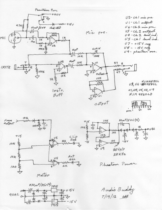
Let’s break it down. First, the mic pre:
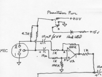
Based on a NJM4580L dual op-amp, the input stage is the same as found in most low-cost gear. Op-amp with gain of 100X (40dB), capacitor coupled to the mic input, and 1K input resistors each side, giving a 2K balanced input impedance.
The non-standard bit is the phantom power. Instead of 48V through 6.8K resistors, there’s 40V through 4.7K. More on this later, since phantom power is one of the known issues with this device. The manufacturer doesn’t claim 48V, just that there is phantom power, and it works with most mics.
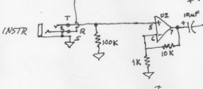
The guitar / instrument input is a simple buffer with a gain of 10X (20dB), and an input impedance of 100K. The jack is shorting on the tip to keep noise out when not in use. The ring is connected to the mic preamp, so it’s shorted out when a guitar is plugged in.
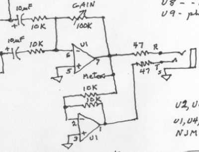
So no, the INSTR jack can’t be used as an insert point for the MIC. The inputs are mixed to a balanced line driver. Not much to see here. Variable gain zilch to 20dB. NJM4560L op-amp.
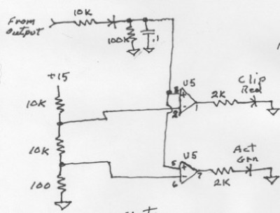
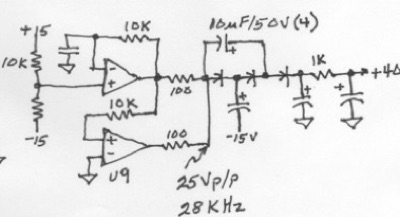
Metering is a couple of LEDs driven off the output thru a diode using another 4560 dual op-amp as comparators.
Next, the problematic phantom power supply:
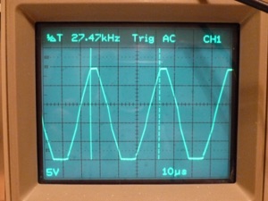
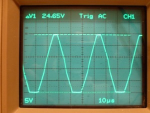
We have another 4560 used as an oscillator and parallel buffer generating a clipped sine wave rail to rail at about 27.5 KHz. This feeds a voltage doubler. Theory says 30V (-15 to +15) X 2 above the -15V rail = 45V, which is within the 48V ± 4V standard for phantom power. However...
As any engineer will tell you, things almost never come out 100%. There are always losses and you get 80% of theoretical if you’re lucky, or you get 150% and the d@# thing burns out.
So, looking at the circuit, it’s apparent there’s no need for the first stage of the doubler which lifts the voltage from -15 to around +10 volts. There is already +15 available. So connect the top of that first 10uF cap to +15, and you may as well remove the first diode. This does a couple of things. It eliminates the op-amp’s voltage drop, so no-load voltage will be a smidge higher, and it eliminates half the current load on the op-amps, so droop under load will be less.
We now have something like this, a single stage charge pump. Under test with a couple of MXL 991 mics, which are pretty current-hungry, we find:
Before After
No load 41.2V 42.5V
1 mic 29.6V 35.0V
2 mics 24.4V 30.8V
We could improve droop further by reducing the 1K resistor and the 100 ohm resistors, but this is pretty good. Cutting the resistors would increase noise on the mic power, and though the frequency is ultrasonic, it might mix with non-linear elements and make audible birdies.
An alternative would be to quadruple the 9V input from the wall wart, but 60 Hz hum is a lot harder to filter, and you’d probably fill the box with electrolytic caps. Speaking of the incoming 9V AC, if you look at the top drawing, you see voltage doublers on plus and minus sides feeding a 7815 positive regulator and a 7915 negative. Not shown are a bunch of 0.1uF ceramic bypass caps scattered around the circuit. That about wraps it up, except I nearly burnt my fingers on the voltage regulators. They run hot, maybe 180°F, so I added heat sinks before I put the box back together.
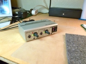
And that’s it - my Audio Buddy. I had assumed that phantom power was from a voltage multiplier on the incoming 9VAC, so why not substitute a 12V wall wart, other than extra heat from the 15V regulators? As it turns out, it wouldn't have had any effect. There's a lot of speculation online, but nobody had actually traced the circuit. It's a compromise. The circuit is cheap and simple and could be improved here and there. Obviously nobody is going to patch this in as a front end to a Neve console. It ain't dirty enough for lo-fi, it's slightly noisy, the gain is low for passive mics, and phantom power is iffy. Whatcha ‘spect for 50 bucks? It is what it is. The steel box is sturdy and well made, the connectors are solid, the knobs and pots look like they'd break if you hit them hard.
So what can be done better? Yeah, the power supply. Voltage doublers are soft. Start with a higher input, say 12 or 15 VAC and go from there. Bigger wall wart to carry around. Better yet, a power supply which runs off 12VDC so the gadget can be battery powered for field use. The mic stage could use a better match between the mic impedance and the op-amp's input transistors. Some folks abhor electrolytic caps in the signal path, preferring $200 silver foil and styrene blocks as big as the whole box, but bigger parts means bigger circuit loops which are interference antennae. An input transformer would help noise figure, but is itself a can of worms. Discrete circuitry can be a better match, or a different IC like T.I.'s mic preamp could be used, but we're not talking a $50 box any more. So you could squeeze a dB or two of noise and a hundredth of a percent THD out of the box. Worth the bother? It’s good enough as is, but maybe some day I'll tinker some more.

