Yet Another BM-800 Circuit Board

Yet Another BM-800 Circuit Board
Thursday, July 23, 2020
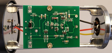
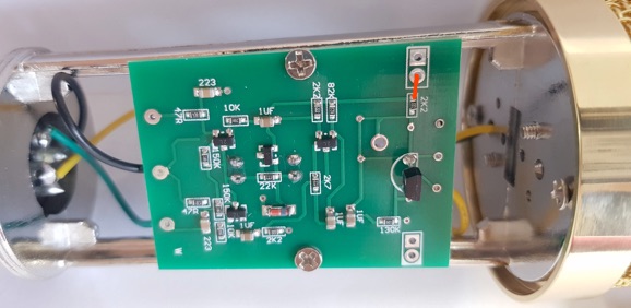
Orcun sent pictures of his BM-800 printed circuit board. His is very much like the ones I have, but certain pads and traces have been removed. Unfortunately, one is a pad we use to connect the large electrolytic filter capacitor.
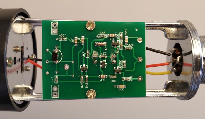
So where should we connect our capacitors?
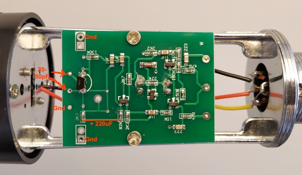
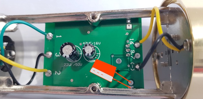
The small 20 to 50 pF NP0 ceramic cap goes from the gate to the drain of the FET as shown. There is no pad to connect the positive lead of the large filter cap to, so it will have to be soldered to one of the SMT resistors, or the green solder mask scraped off the copper trace and the lead attached there. The negative lead of the cap connects to any ground pad.
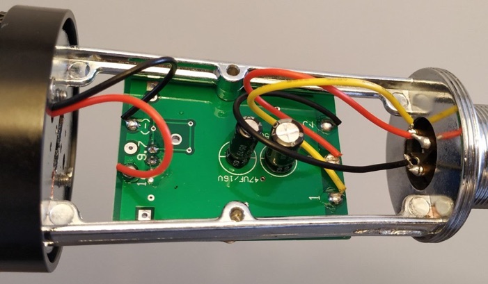
For reasons of space, maybe put the cap on the back of the board with the other electrolytics, and feed the + lead thru the hole in the PC board something like this?
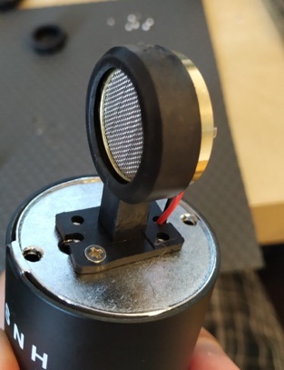
Orcun fitted his new 25mm capsule into the original holder.
He reports that changing the capsule made a big improvement in the sound of his mic. The capacitors reduce noise and distortion, making his $16 mic sound like a much more expensive model.
+
--


Thanks, William for additional pictures.

