LIKA (Modified Octava circuit)

Johnny Zhivago’s Lika
Friday, March 4, 2016
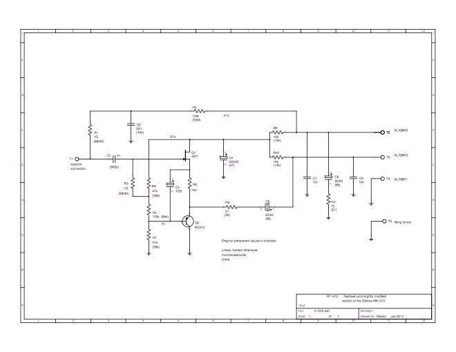
John Bierman, aka Johnny Zhivago, is another contributor to the micbuilders forum. He has built a lot of mics of various types over the last few years, and sent me one of his recent designs based on a modification of the Octava MC-012 circuit. See Scott Dorsey’s mod article in Recording Magazine here. An excellent discussion of this circuit is at http://groupdiy.com/index.php?topic=41986.0 John based this mic on Robert Russell’s revision of the circuit (schematic below). You can find more about John’s mics at http://www.tlahtolli-audio.com.
The Octava MC-012 circuit is a minimum-parts impedance converter with a JFET source follower input stage and a PNP emitter follower output stage driving pin 3 of the mic cable. Pin 2 in the mic is terminated with a resistor and capacitor to match the impedance at pin 3. Any hum or noise picked up by the cable should be equal on both pins at the mic preamp, and will cancel due to the preamp’s balanced input. In practice, it works OK for normal short cable runs. For long cables, situations where there may be a long snake between mics and the mixer, there can be problems.
An interesting feature of the Octava circuit is that both stages are in series as far as the DC power supply is concerned, and therefore have the same current flowing. The JFET’s Idss or zero bias current pretty much determines the current, which is pretty standard for the input stage of FET mics. The output stage of most mics is biased slightly higher for a bit more output current capability. With a typical J305 or 2N3819 JFET, the Octava circuit runs about 2 mA which is adequate. The J201 in the particular mic I tested has a lower Idss around 0.2 mA, resulting in about 0.3mA current thru the transistors. This probably had some effect on distortion and output capability. The mic was stable and showed no tendency to oscillate, although there was a low frequency low level “thump” or popcorn noise which went away after a couple of minutes. Noise and output capability should theoretically be better with the higher operating current of the original Russian version.
So how did it measure? John had added a .001uF cap from the PNP’s base to ground to EQ the top end of the capsule, which was a typical 32mm cardioid-only affair like those in MXL’s low end mics. Those capsules usually have a strong 10-12 KHz peak.
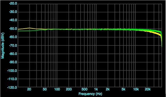
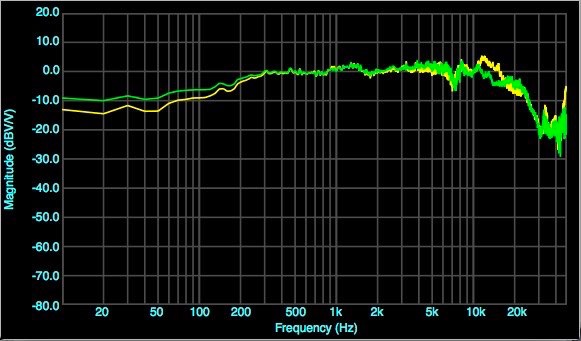
First, electronic frequency response to white noise with & without EQ. Yellow, with cap. Green w/o cap. Basically a flat response circuit.
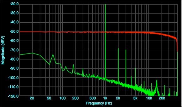
Frequency response and harmonic distortion as received. Harmonics are almost 50dB down, 0.3%
Acoustic response of original capsule with EQ (yellow) and RK-47 capsule no EQ (green).
I didn’t have a reference for John’s capsule, so I tried an RK-47 capsule. Removed the 0.001 cap from base of the PNP to ground, because an RK-47 doesn’t need any HF roll-off. The RK-47 has an upper mid rise and no HF peak. More bass. Both capsules show a 7KHz notch that I haven’t seen before. Something to do with this particular headbasket? This one is painted instead of plated like the other K-5000 bodies I’ve seen, and there are patches of rust on the inner layer of screen. Odd. I cleaned the rust off as well as I could and tried to tidy up the edges of the inner screen which were a bit loose.
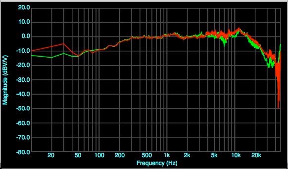
Then I put the original capsule back, but did not reinstall the .001 EQ cap. Red, resulting response. Green, response as originally received. The 7KHz notch is much lessened, so it may have been related to the inner layer of screen. The mic is brighter as expected, but the 12KHz peak isn’t any higher.
Experiments follow to look at the effect of the headbasket, in the next article.