Mic EQ Pt.4

EQ Pt.4 - Noise
Monday, February 10, 2014
Continuing the exploration of adding high frequency roll-off to generic transformerless mics:
We added series resistors between the phase splitter FET and the emitter follower line drivers, then put a variable RC network between the inverted and non-inverted phase.
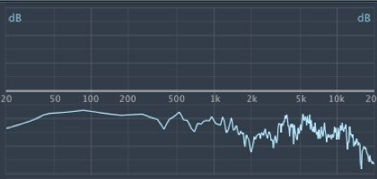
Not all microphone capsules are flat. Sometimes they need electronic equalization.
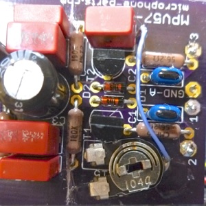
Here’s one implementation on a Microphone-Parts MPV57 printed circuit board. C14 is a 1000pF film cap, at the top of the picture with the blue wire going to one terminal. That terminal originally went to ground, but the pin is bent upward so it doesn’t contact its pad, and a bit of urethane glue holds the cap in place.
A 100K pot is connected at one end to the C15 pad which goes to T1’s base. The wiper of the pot connects to C14 with the blue wire. A couple of dabs of glue hold the wiper and free terminals of the pot to the circuit board. You can see where the traces were cut between C3 & C4 and the base resistors. 10K resistors were soldered to the back of the board.
Back to the topic of noise. Obviously, there is some noise associated with these resistors in the signal path. Because of that, we want to keep the resistors fairly small. OTOH, a larger resistor will have less loading effect on the FET, T3, and will require a smaller capacitor at C14. I picked 10K as a workable compromise.
So. On to the workbench to make measurements. Incidentally, the bench setup is mic via a short 1m cable into my TASCAM US-144 mk II USB interface. Unless stated otherwise, the gain is set so 1V at the mic input = 0dB on a graph, though sometimes I make multiple measurements and offset one just to make the graph easier to read. Where I say measurement from pin2 to pin3, I have a normal balanced cable. When I measure from pin2 to pin1 unbalanced, I unsolder the wire from pin3 at the PCB inside the mic, and solder it to ground, so only pin2 is feeding the preamp. Vice versa to measure output at pin3. There’s nothing fancy about the setup. The interface measures almost flat from 10Hz to 45KHz at 24/96 sampling, with a few spikes of digital bit noise at subharmonics of the sampling rate, and a trace of 60Hz hum always gets into the setup.
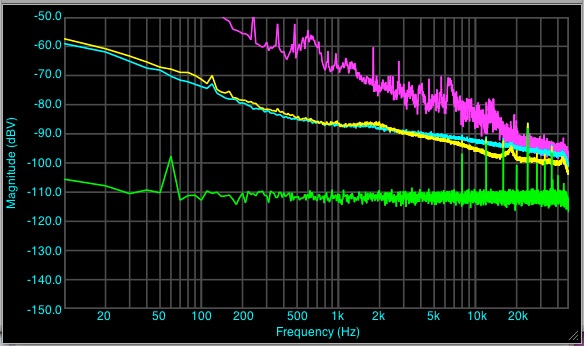
In order to see the noise from the electronics, the RK-87 capsule was disconnected and replaced with a 68pF NPO capacitor. Measured from 10 Hz - 48 KHz, TASCAM US-144 mkII 24/96 at full 60dB of gain. Mic case closed normally.
Yellow - noise without 10K resistors, with C14 = C15 = 470 pF (normal circuit)
Cyan - noise with 10K resistors, with C14= 470 pF and trimpot = 35K (close to a U87 curve)
Green - noise floor of I/F with 220Ω shorting plug in mic input.
Violet - noise with RK-87 capsule in circuit, without resistors, quiet room at night, mic in foam sleeve, holding my breath. Pretty much same with and without Rs.
Conclusions: noise is slightly less below 500 Hz (surprise! but repeatable) and a bit more above 5 KHz. Pretty much buried in the brown noise of air molecules bouncing off the capsule when it is connected. Air noise drops off pretty sharply above the RK-87's 13 KHz peak.
Some of the HF drop off without resistors is due to C14 & C15, but I put them back in circuit because that's the default to compare against. If I had cranked in more rolloff with the trimpot, it might have measured closer, but 25K - 50KΩ is flattest with an RK-87 capsule.
Conclusion: there is no audible added noise with this means of controlling a mic’s high frequency balance. Noise of air molecules in the capsule predominates.

