The Spamplifier

The Spamplifier
Saturday, March 6, 2021
I want to attempt to measure the distortion produced by capacitors. There is an awful lot of talk about how capacitors sound, and how they may distort audio passing through them. I suspect a lot of the talk is opinions based on hearsay, expectation bias, and claims of snake oil salesmen. On the other hand, it is definitely possible to pick the wrong capacitor for a particular job, and the results will be audible. The distortion produced by a typical capacitor properly used is very small, measured in parts per million or parts per billion, so the measurement system needs to be extremely clean and accurate. With luck, a modern 24-bit digital computer interface will be accurate enough. We will need a fair bit of current though, to force a signal across a capacitor at high frequencies. For that, I hope taking a bunch of NE5534 op-amps in parallel will provide enough current with distortion in the parts per million range.
Taking a page from Nelson Pass and “The Beast Of A Thousand JFETs” I made a wanna-beast of 16 NE5534s. It should provide 2 channels of 4 watts each as a headphone booster, or one channel of 8 watts for capacitor testing. If we’re REALLY lucky, maybe some of the noise, distortion, and offset voltage will cancel among the batch of op-amps. Maybe not. Wait and see.
I need a high current buffer amplifier for measuring capacitor distortion. The distortion is very small, so the signal source and buffer amp have to add very little distortion of their own.
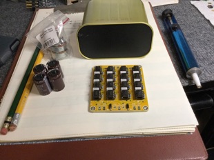
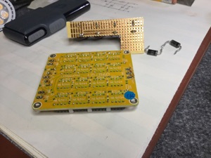
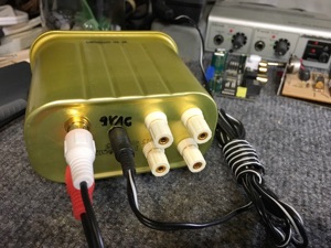
First item, a circuit board from eBay with sockets for 16 X 8-pin DIP op-amps. Some filter capacitors for the power supply. Bipolar, +/- 12 to 15VDC will do the trick. I have a couple of 9VAC wall wart transformers, so that part is taken care of.
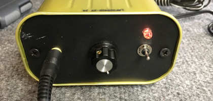
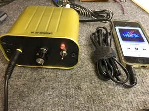
A volume control might be handy, but is not an absolute necessity, since the gadget will be unity gain. Some jacks for ins and outs. A box to put it in. Nothing on hand. Well, there IS an empty SPAM can in the recycle bin . . .
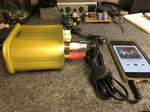
And so construction begins on the SPAMplifier. The SPAM can is thin aluminum, and the bottom oilcans with a snap when you push on the sides. Insulation for the stuff which will be stuck inside is also desirable, so a sheet of gosh-awful pink sticky-back foam is used to line the box and make it feel and sound less tinny. L-brackets for attaching the front panel are glued to the sides. Jacks for speaker leads, power input, and RCA audio inputs are mounted on the bottom or back side. The front panel is a piece of plastic cut to fit. For shielding, it’s covered with copper tape. An earphone jack, volume control, power switch, and LED are mounted on it.
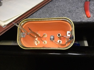
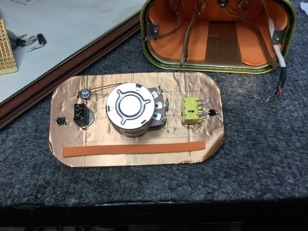
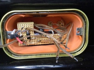
The power supply capacitors, diodes, and resistors are soldered to a small piece of prototype board. A quick test fit determines that it’s gonna be a tight fit, but it should be possible to cram everything into the SPAM can.
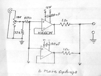
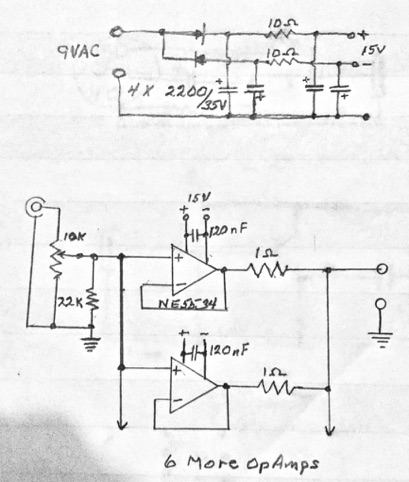
So here is the schematic of one channel and power supply. I should mention that I have a few reservations about details of the eBay Chinese circuit board, but it works as is.
A listen with various headphones proves it’s a really good headphone amp.
From the specs of the NE5534 we should expect response to extend from DC to several megahertz, distortion to be almost unmeasurable, and angels to dance as we play music. I didn’t see angels, but the music was heavenly.
More photos. Measurements to follow in the next installment.
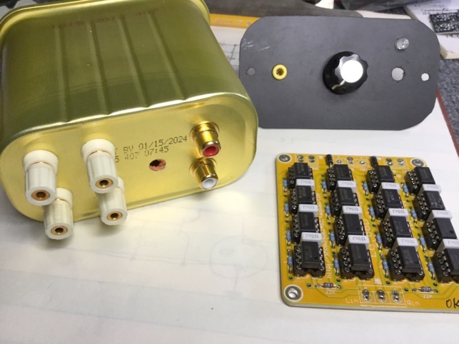
Is YOUR amplifier past its “SELL BY” date?