Karaoke mics (again)

Another Chinese mic Circuit
Thursday, December 18, 2014
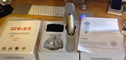
The inexpensive electret mics I have been buying for chassis have a surface mount electronics module with a modified Schoeps circuit. Out of curiosity, I hooked one up on the test bench to see how it compares with the “standard” version of the circuit. First, the schematic:
A deeper look at the circuit of the inexpensive Chinese electret Karaoke mics from eBay.
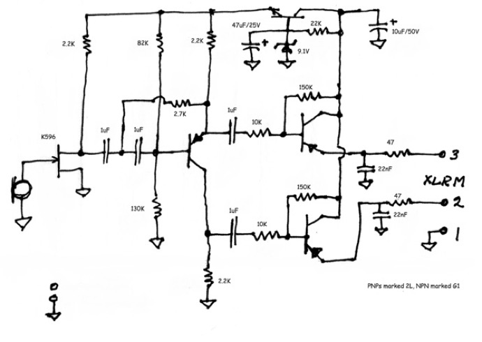
There are several novel features. The first stage FET is used as a common source voltage amplifier instead of a phase splitter, so the circuit has voltage gain, and without local feedback, distortion may be present. The FET used is intended for electret capsules and has a very low input capacitance (good) but also an internal diode which is intended to replace the gate bias resistor. You know, the one gigohm resistor from gate to ground in most mics.
The second stage is the phase splitter consisting of a PNP transistor with equal emitter and collector load resistors. There is a low-cut network at the input consisting of the two 1uF capacitors and 2.7K resistor.
The output stage is standard Schoeps emitter followers which provide current gain and also power the rest of the circuit with their collector current. The output stage is biased at a lower static current than usual, giving a higher collector voltage.
At the top of the drawing, a transistor, zener diode, and a pair of electrolytic caps make up the voltage regulator for the first two stages. Usually, there is a simple resistor and zener here. This arrangement allows the mic to work with the unbalanced 5V phantom power from a computer sound card’s mic input or balanced 48V phantom power from a standard mic preamp.
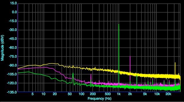
So how does it measure? How does it compare with an optimized Schoeps circuit?
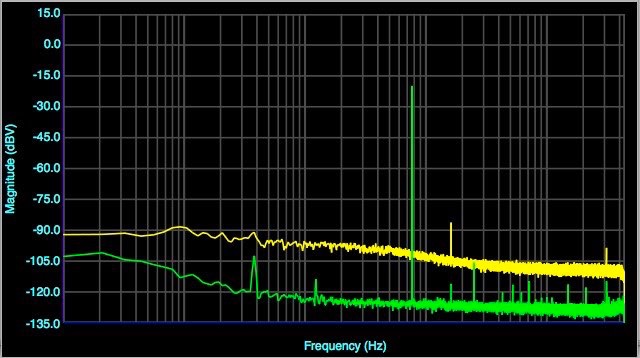
The yellow trace is the karaoke mic at 100mV (-20dBV) out vs a Microphone-Parts V57 (green).
The first thing you notice is the M-P circuit is 20dB or more quieter. The karaoke mic has some second harmonic distortion, around 0.02%. Where does the noise come from? Maybe it’s the FET. The type K596, vs the J305 in the M-P circuit. So we replace the FET with a J305 and find:
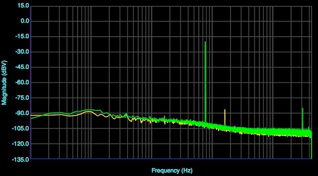
The noise is essentially unchanged. The J305 (green) does have less 2nd harmonic distortion.
Maybe the noise is from the “extra” second stage transistor. If we hook up the FET with a source load resistor, it can be the phase splitter as well as input stage, and the second stage eliminated.
The 3-transistor Schoeps-style input (green) is a little quieter in the bass than the 4-transistor version (blue), but not even close to the Mic-Parts V57 (yellow).
Where does all that noise come from? Turns out, it comes from the voltage regulator. The transistor amplifies the noise from the zener diode and of course generates some noise itself. Oops! placing an RC filter of 330 ohms and 220 uF between the regulator transistor’s emitter and the low level stages gets rid of most of the noise.
With the DC supply filter but otherwise stock circuit in place (red), noise (yellow) is much reduced, and approaches the M-P circuit (green), which is built of top-shelf cost-be-damned components.
With a K596 FET, the second harmonic is still present. The circuit could be looked at as a U87a / KM84 first stage, followed by a solid-state 2:1 transformer which provides the balanced output.
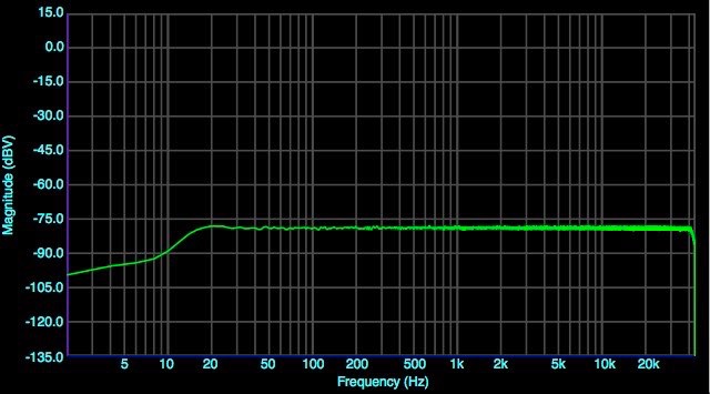
The remaining measurement is frequency response, which is flat measured with white noise above the 20Hz second order low-cut filter frequency.
All of these electret mics based on this circuit have polarity reversed from standard, that is, the wires to pins 2 & 3 of the XLR are backwards. That should be fixed so it will mix with the rest of your mics. But you check polarity on every mic you build or buy anyway, don’t you?
So this is not a bad circuit except for the noisy voltage regulator. If you like a bit of harmonic enhancement at high SPL, like a U87 at rock-n-roll levels, you’ll probably like the K596 FET. As shipped, the circuit provides about 10dB more voltage gain than a “standard Schoeps” circuit, so it’s more likely to overload a mic preamp, and may be too hot with a large diameter capsule.
These little problems can be cured with tweaks here and there. Adapting the ideas to a no-holds-barred studio mic will be interesting. More to come.

